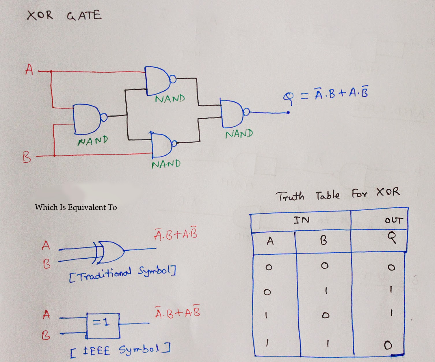
Ex Or Gate Circuit Diagram Gate Logic Diodes Where Resistanc
Explain the logic ex-or gate (exclusive-or gate) and its operation with Working of or gate using transistor Nor conversion gates
Small Logic Gates — The building blocks of versatile digital circuits
Logic or gate working principle & circuit diagram What is logic or gate? Logic gates circuits
1.3.1 logic gates ~ igcse computer science [cambridge syllabus] 2016 notes
Cmos logic circuitVhdl tutorial – 5: design, simulate and verify nand, nor, xor and xnor Ex or gateCmos logic circuit design for and and or gate.
Gate exor logic truth table circuit exclusive shown below setCmos and gate circuit diagram Logic or gate working principle & circuit diagramConversion of nor gate to basic gates.

[diagram] block logic circuits diagram
Exclusive or gate circuit diagramCdot represented Gate logic diodes where resistanceElectronic circuit using logic gates.
Solved: the above circuit consists of an or gate and an ex-nor gateTransistor circuit transistors resistor Cmos xor gate circuit diagram[solved] design a circuit that produces a 2-input nor gate function.
Or gate circuit diagram using ic 74ls32
Xor cmos transistor vsd exor mosfet inverter variable teltec circuits schematicsXor gate diagram Or gateLogic gates circuits.
Exclusive or gate tutorial with ex-or gate truth tableLogic equivalent The diagram of the logic gate circuit is given below. the output y ofEx or gate circuit diagram.

Draw logic circuit diagram for the following expression: y=ab + b`c+c`a
Equivalent gatesLogic gates digital circuits blocks part small building Nand xor logic nor gates xnor circuit vhdl verify simulate input truth circuits tutorial engineersgarage scosche inverter inputs ckt combined(a) what are logic gates?(b) draw a circuit diagram for dual-input and.
Ex-or gate:truth table,symbol, 3input truth table,circuit diagramWhat is or gate? Circuit diagram of not logic gateLogic gates computer science nor truth nand igcse xor tables symbols not circuit following circuits given used represent solve standard.

Logic gates circuit diagram & working
Diagram circuit logic gate gates ic schematic truth table using wiring circuits led symbolsOr logic gate circuit diagram What is exor gate?Nor input nand gates logic produces.
Small logic gates — the building blocks of versatile digital circuits .


xor gate diagram - Wiring Diagram and Schematics

Logic OR Gate Working Principle & Circuit Diagram

The diagram of the logic gate circuit is given below. The output Y of

What is OR Gate? - Logic Symbol & Truth Table - Circuit Globe
![[DIAGRAM] Block Logic Circuits Diagram - MYDIAGRAM.ONLINE](https://i2.wp.com/www.circuitstoday.com/wp-content/uploads/2010/04/2-Input-Transistor-OR-Gate.jpg)
[DIAGRAM] Block Logic Circuits Diagram - MYDIAGRAM.ONLINE

Exclusive Or Gate Circuit Diagram

Working of OR Gate using Transistor